Introduction
Wire bond inspection is not a single measurement task.
Depending on the package design and process requirements, an engineer may need to inspect the appearance of a bond, measure wire diameter, verify bonding position, check wire spacing, or determine the height and profile of a wire loop.
These requirements may look similar under a microscope, but they do not necessarily require the same measurement capability.
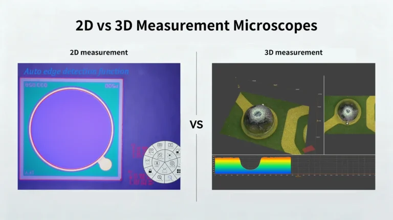
A conventional optical microscope may be sufficient for visual inspection. A 2D measuring microscope can be appropriate when the required dimensions are mainly in the X-Y plane. When height or depth becomes part of the inspection specification, an XYZ measuring microscope may be more suitable. For applications requiring complete wire geometry, height distribution, or surface-profile information, a 3D measuring microscope can provide additional dimensional information.
The right choice therefore depends less on the maximum magnification of the microscope and more on what needs to be observed, what needs to be measured, and whether the measurement includes the Z axis.
For an overview of microscope configurations used for wire bond inspection and measurement, see our wire bond inspection microscope solutions.
Table of Contents
What Needs to Be Inspected in a Wire Bond?
A wire bond is a three-dimensional structure rather than a flat feature.
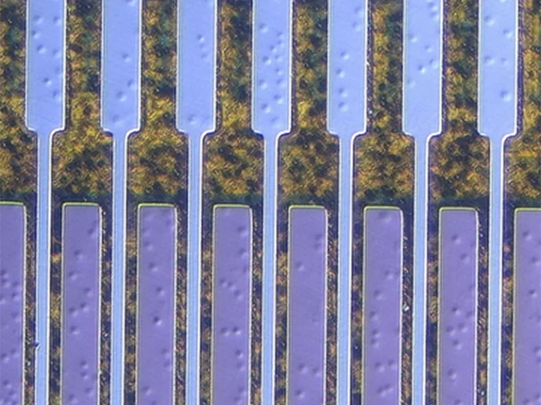
A typical wire bond includes the bond area, wire span, loop, and second bonding point. Depending on the package and bonding process, engineers may need to evaluate both planar dimensions and vertical geometry.
Common inspection and measurement parameters include:
- Wire diameter
- Bond size
- Bonding position
- Bond pad dimensions
- Wire-to-wire spacing
- Wire-to-pad clearance
- Wire loop height
- Wire loop shape
- Wire deformation
- Wire sagging
- Bond alignment
- Surface or height variation
Industry guidance and semiconductor packaging literature also distinguish visual inspection from dimensional and mechanical tests. Visual inspection can verify bond placement, bond appearance, and wire clearance, while other methods are required when quantitative parameters such as loop height or bond strength need to be evaluated.
This distinction is important when selecting a microscope.
The first question should therefore be:
What information does the inspection process actually require?

Visual Inspection or Dimensional Measurement?
Not every wire bond inspection requires coordinate measurement.
When Visual Inspection Is Sufficient
If the primary purpose is to identify obvious visual defects, a high-resolution optical microscope may be enough.
Typical tasks include:
- Checking whether the wire is present
- Inspecting bond appearance
- Identifying obvious wire deformation
- Observing contamination
- Checking bonding areas
- Verifying general bonding consistency
The microscope provides the image needed for an operator or inspector to make a visual judgment.
However, visual inspection becomes less suitable when the decision depends on a numerical tolerance.
For example:
Is the wire diameter within specification?
Is the bond position within tolerance?
Is the loop height within the process range?
These questions require measurement rather than observation alone.
When Dimensional Measurement Is Required
When a wire bond inspection involves quantitative dimensional requirements, a measuring microscope can provide calibrated X-Y or XYZ coordinates.
Typical 2D measurements include:
- Wire diameter
- Bond diameter or size
- Bond position
- Wire spacing
- Pad dimensions
- Distance between bonding points
When height is also important, Z-axis measurement becomes relevant.
This is especially important because a wire loop may appear acceptable in a top-view image while having a different vertical profile.
Recent industry discussions around 3D wire-bond inspection similarly identify loop height, loop profile, wire deformation, clearance, and wire-to-die relationships as parameters that cannot always be fully described by X-Y information alone.
2D, XYZ or 3D? Start With the Measurement Requirement
A useful way to choose a microscope is to classify the required measurement according to the dimensional information it needs.
| Inspection Requirement | 2D Measurement | XYZ Measurement | 3D Measurement |
|---|---|---|---|
| Wire diameter | ✓ | ✓ | ✓ |
| Bond size | ✓ | ✓ | ✓ |
| Bond position | ✓ | ✓ | ✓ |
| Wire spacing | ✓ | ✓ | ✓ |
| Bond pad dimensions | ✓ | ✓ | ✓ |
| Loop height | — | ✓ | ✓ |
| Step height | — | ✓ | ✓ |
| Vertical clearance | — | ✓ | ✓ |
| Wire loop profile | Limited | Limited | ✓ |
| Surface profile | — | Limited | ✓ |
| Height distribution | — | Limited | ✓ |
| Complete 3D geometry | — | — | ✓ |
The important point is that 3D capability is not automatically required for every wire bond application.
If all critical dimensions are measured in the X-Y plane, 2D measurement may be sufficient.
If specific height or depth measurements are required, an XYZ system may provide the necessary capability.
If the inspection requires a broader understanding of the wire’s three-dimensional geometry, a 3D measurement system becomes more relevant.
How to Choose a Microscope for 2D Wire Bond Measurement
When 2D Measurement Is Enough
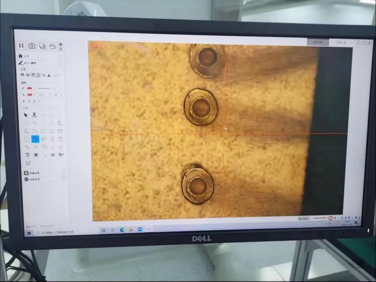
A 2D measuring microscope is suitable when the important features can be defined within the X-Y measurement plane.
Examples include:
Wire Diameter
The apparent diameter of a bonding wire can be measured from a calibrated image when the wire is adequately resolved and its edges can be identified.
Bond Size
Bond dimensions can be measured by locating the relevant edges or boundaries.
Bond Position
The X-Y coordinates of the bonding point can be compared with the intended position.
Wire Spacing
The distance between adjacent wires or between a wire and another feature can be quantified.
Bond Pad Dimensions
Pad width, length, spacing, and other planar dimensions can be measured without requiring Z-axis information.
For these applications, adding full 3D measurement may not provide meaningful additional information.
The engineering requirement should determine the measurement configuration.
When Should You Choose an XYZ Measuring Microscope?
Height and Depth Change the Measurement Problem
The key reason to consider an XYZ measuring microscope is simple:
The inspection specification includes a Z-axis dimension.
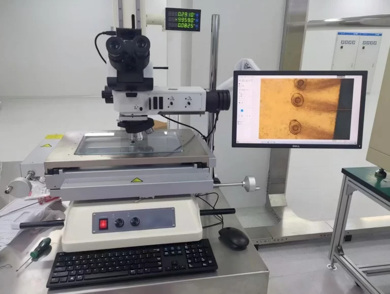
An XYZ system provides coordinate information along X, Y, and Z.
This allows engineers to measure not only planar dimensions but also height differences between selected points or surfaces.
Typical applications include:
- Wire loop height
- Vertical clearance
- Step height
- Feature height
- Surface-to-surface distance
- Recess depth
For example, if two bonding features have similar X-Y positions but different heights, an XY-only system cannot directly quantify their vertical difference.
The Z axis provides that additional information.
Wire Loop Height Is a Typical XYZ Measurement
Wire loop height is one of the clearest examples of why Z-axis measurement can matter.
The loop rises above the package or die surface before returning to the second bond. Its height and geometry can influence available clearance and package design constraints.
Loop height is also an established measurement parameter in wire-bonding evaluation. Optical measuring systems are used specifically for measuring the highest point of wire loops, while other inspection methods can also quantify wire-loop height.
For an engineer, the measurement question may be:
What is the maximum height of this loop relative to the reference surface?
That is fundamentally different from measuring wire diameter or bond position.
The first is a Z-axis problem.
The second is primarily a 2D problem.
Why XYZ Can Be a Practical Middle Ground
Not every application that requires Z information needs a full surface reconstruction.
An engineer may only need to measure:
- Point A height
- Point B height
- Difference between two surfaces
- Maximum loop height
- Step height
In these situations, an XYZ measuring microscope can provide the required coordinate information without turning every inspection task into a full 3D surface-analysis workflow.
For example, a precision XYZ measuring microscope can combine X-Y dimensional measurement with Z-axis height and depth measurement for semiconductor package structures.
This makes XYZ measurement particularly useful when the inspection combines conventional dimensional measurement with selected height measurements.
When Is a 3D Measuring Microscope More Appropriate?
Measuring the Shape, Not Just One Height
There is an important distinction between:
Measure the height of one feature
and:
Understand the geometry of the entire feature.
An XYZ system can measure selected coordinates.
A 3D measurement system can provide broader information about a surface or three-dimensional structure, depending on its measurement technology and software.
For wire bonding, this can include:
- Wire loop profile
- Height distribution
- 3D geometry
- Surface profile
- Vertical deformation
- Height variation
This can be particularly useful when the maximum loop height alone does not fully describe the bonding structure.
Why Wire Geometry Can Require 3D Information
A wire bond does not simply rise vertically from one point to another.
The wire forms a curved trajectory between bonding points.
Two wires may have similar X-Y positions but different:
- Loop heights
- Curvature
- Sagging
- Clearance
- Vertical trajectories
A top-view image can show where the wire is located, but it does not necessarily reveal the complete vertical geometry.
This is one reason recent semiconductor packaging work has focused on 3D measurement of wire-loop height, shape, and position as package density increases.
For applications where the complete wire profile matters, 3D measurement can therefore provide information that conventional 2D inspection cannot.
What Microscope Specifications Should Engineers Check?
Choosing between 2D, XYZ, and 3D is only the first step.
The microscope should also be evaluated against the actual measurement conditions.
Optical Resolution
The smallest wire or bond feature determines part of the required optical resolution.
Higher magnification alone does not guarantee better measurement.
The optical system must provide sufficient resolution and contrast to identify the feature being measured.
Measurement Accuracy
Resolution and accuracy are not the same.
A microscope may display very small measurement increments while its actual measurement accuracy is influenced by:
- Optical distortion
- Calibration
- Stage accuracy
- Mechanical stability
- Temperature
- Image processing
- Edge detection
For dimensional inspection, engineers should evaluate accuracy under defined measurement conditions rather than selecting equipment based solely on a resolution specification.
Repeatability
Repeatability becomes particularly important when the microscope is used for quality control or process monitoring.
If the same wire is measured multiple times, the results should remain sufficiently consistent.
This is also important when different operators use the same system.
A measurement method that depends heavily on subjective point selection may introduce operator-to-operator variation.
Z-Axis Performance
For loop-height measurement, engineers should pay particular attention to:
- Z-axis resolution
- Z-axis accuracy
- Z-axis repeatability
- Focusing method
- Surface detection
- Measurement range
The appropriate specification depends on the required tolerance and the geometry of the wire.
A smaller Z increment is not automatically equivalent to better measurement accuracy.
Illumination and Surface Contrast
Wire bonding often involves reflective metallic surfaces.
Gold, copper, aluminum, and other bonding materials can produce strong reflections under inappropriate illumination.
This can make the apparent edge of a wire or bond difficult to define.
Therefore, the illumination system should be considered together with the optics and camera.
Possible approaches may include:
- Brightfield illumination
- Darkfield illumination
- Coaxial illumination
- Directional lighting
- Polarized observation
The goal is not simply to make the image brighter.
The goal is to produce a stable, interpretable image from which the required feature can be identified and measured.
A Practical Microscope Selection Guide for Wire Bond Inspection
The selection process can be simplified into four questions.
Question 1 — Do I Only Need Visual Inspection?
If yes, prioritize:
- Optical resolution
- Image quality
- Depth of field
- Illumination
- Ergonomics
A conventional high-resolution inspection microscope may be sufficient.
Question 2 — Do I Need X-Y Dimensional Measurement?
If the requirements include:
- Wire diameter
- Bond size
- Bond position
- Wire spacing
- Pad dimensions
then a calibrated 2D measuring microscope may be appropriate.
Question 3 — Do I Need Height or Depth?
If the requirements include:
- Loop height
- Step height
- Vertical clearance
- Depth
- Height difference
then an XYZ measuring microscope should be considered.
Question 4 — Do I Need Complete 3D Geometry?
If the inspection requires:
- Wire loop profile
- Surface profile
- Height distribution
- Complex 3D geometry
- Detailed vertical deformation
then a 3D measuring microscope may be more appropriate.
The decision can therefore be summarized as:
Visual inspection → Optical microscope
Planar dimensional measurement → 2D measuring microscope
X-Y + selected height/depth measurement → XYZ measuring microscope
Surface geometry and broader 3D analysis → 3D measuring microscope
This approach starts with the measurement task rather than the instrument specification.
Common Mistakes When Selecting a Wire Bond Inspection Microscope
Choosing Based Only on Magnification
A high magnification number may look attractive on a specification sheet, but magnification does not tell you whether the system can provide the required measurement accuracy.
The optical resolution, field of view, working distance, camera performance, and measurement system all matter.
Assuming Every Wire Bond Requires 3D
Wire bonding is inherently three-dimensional, but that does not mean every inspection task requires a 3D measurement system.
If the requirement is simply to measure wire diameter or bond position, 2D measurement may be sufficient.
3D becomes valuable when the inspection decision depends on vertical geometry.
Confusing EDF With 3D Measurement
Extended Depth of Field can produce an image with a greater apparent depth of focus by combining multiple focal planes.
This can be very useful for observing wire structures with significant height variation.
However:
A fully focused image is not automatically a 3D measurement dataset.
EDF improves visualization across different focal planes.
3D measurement provides quantitative information about geometry.
They can complement each other, but they should not be treated as identical technologies.
Ignoring Calibration and Repeatability
A system may produce visually excellent images but still be unsuitable for dimensional quality control if calibration, accuracy, or repeatability does not meet the application requirements.
For production inspection, measurement consistency is often just as important as image quality.
2D, XYZ or 3D: Which One Is Right for Your Application?
There is no universal “best” microscope for wire bond inspection.
The appropriate configuration depends on the highest-dimensional requirement in the inspection process.
| If You Need to Measure… | Consider |
|---|---|
| Wire appearance | Optical microscope |
| Wire diameter | 2D measurement |
| Bond size | 2D measurement |
| Bond position | 2D measurement |
| Wire spacing | 2D measurement |
| Loop height | XYZ / 3D |
| Vertical clearance | XYZ / 3D |
| Step height | XYZ / 3D |
| Loop profile | 3D |
| Height distribution | 3D |
| Complete wire geometry | 3D |
The practical rule is simple:
Choose the measurement capability based on the information required by the inspection specification, not simply the maximum capability of the microscope.
This prevents two common problems.
First, engineers may select a system that is more complex than necessary for a relatively simple 2D inspection task.
Second, they may select a conventional optical system only to discover later that a critical Z-axis measurement cannot be performed.
Conclusion
Choosing a microscope for wire bond inspection starts with understanding the measurement task.
A high-resolution optical microscope may be sufficient when the goal is visual inspection.
A 2D measuring microscope is appropriate when the critical dimensions are primarily located in the X-Y plane, such as wire diameter, bond size, bonding position, or wire spacing.
An XYZ measuring microscope becomes more relevant when height, depth, or vertical distance is part of the inspection specification. Wire loop height is a typical example.
A 3D measuring microscope becomes useful when engineers need broader information about wire geometry, surface profile, height distribution, or other three-dimensional characteristics.
The selection should therefore consider more than magnification. Optical resolution, measurement accuracy, repeatability, calibration, Z-axis performance, illumination, and software workflow all contribute to the reliability of the final measurement.
Most importantly, the microscope should be selected after defining what needs to be measured.
The right question is not:
“Which microscope has the highest specification?”
It is:
“Which measurement capability provides the information I need to make the engineering decision?”
For a broader understanding of wire bond defects, inspection challenges, and the role of 3D inspection, see our Wire Bond Inspection Guide: Common Defects, Inspection Challenges and 3D Inspection Solutions.